At all stages of aerospace design, engineers find themselves using models of increasing complexity. In turn, this generates a requirement on software vendors to create packages that can take more of the work off the users by streamlining or even automating processes.
Software that is easier to use allows engineers more time to focus on simulation and analysis of the data rather than trying to adapt to new software, learn proprietary coding languages, or the worrying about how to map algorithms to the latest GPU or accelerator technology.
At one level, the move to more user-friendly software can be as straightforward as migrating legacy code from Fortran to newer, more intuitive languages such as Matlab. In complex aerospace design problems, on the other hand, sophisticated software that can automate much of the process of optimising designs can shorten development times and make design engineers more productive. Sometimes, the benefits in aerospace engineering come not solely from the software alone but by coupling the package to novel manufacturing techniques such as 3D printing.
Aircraft noise has become a major concern and in some cases is an obstacle to growth in air transport as numbers of airports place restrictions on the amount of noise that can be generated by an aircraft.
Designers and engineers must work hard to reduce the noise of jet engines by placing acoustic liners in the nacelle, a housing that holds engines, or equipment on an aircraft, to minimise the fan noise radiated from the engine.
One example of the use of MSC software for acoustic simulation looked at the use of nacelle liners on Airbus aircraft. The company evaluated several different shapes and materials to understand the best performance.
Airbus found that it could dramatically reduce the time required to design and evaluate acoustic liners by moving to a simulation-based process using Actran acoustic simulation software developed by Free Field Technologies (FFT), a subsidiary of MSC.
Diego Copiello, MSC product marketing manager and senior application engineer, said: ‘Liners are absolutely fundamental to the aircraft design. If you want to reduce the noise generated by the engine, the most efficient technology that you can apply in the nacelle is to use the liners.’
The design of the nacelle itself is made more difficult by several factors, first of which is that the final geometry of the nacelle may not yet be finalised, so any design may have to accommodate changes in the shape of the nacelle in which it is housed.
Another restraint is the materials that can be used for the nacelle liner, as Copiello explained: ‘You cannot use a porous material on a nacelle for example, because porous materials absorb and keep the water or kerosene so there is a risk of ice formation or there is a fire hazard.’
Copiello went on to highlight how this restricts the potential design options available to engineers looking to optimise the design of these liners for commercial aircraft, as they have no choice but to innovate when designing the geometry of the liner to allow for the greatest increase in performance.
Even a small part of an aircraft, which at first glance may seem insignificant, often requires several simulations and a delicate balance must be struck between performance, cost and weight. Another often overlooked layer of complexity is in the combination of different disciplines or different types of data that need to be integrated to provide a clear picture of the overall behaviour of the system. This could take the form of FEA, CFD, or thermal analysis as well as acoustic.
To combat increasing complexity, software developers abstract complexity or completely automate features that traditionally would have required many man-hours’ work in repeating experiments or simulations. In the case of Airbus, the engineers found they could automate the optimisation process when designing the nacelle liners.
Copiello said: ‘So the automated liner optimisation chain basically gives Airbus the possibility to run everything automatically.’
The team at Airbus developed an integrated numerical chain for Actran in order to streamline its use by acoustics engineers. The chain, called the Automated Liner Optimization Chain for Nacelles Air Inlets and Exhausts (ANaNax), automated the simulation process from engine geometry to results.
A typical optimisation loop for the nacelle liner requires evaluation of 80 liner iterations and three flight conditions at a frequency range from 125Hz to 5650Hz, which means several thousand different iterations.
Increasingly usability is a primary concern of many software providers but sometimes it is the convergence of two different areas of technology that provide the ease of use – as is the case with the convergence of topology optimisation and additive manufacturing.
This technology is now seeing much more use in industry due to the synergies with additive manufacturing or 3D printing, as it is commonly known. Franck Mouriaux, general manager, structures, at RUAG Space, said: ‘The advantage of additive manufacturing is that it gives us more freedom for the designer, and allows us to elaborate more complex shapes and this is really well suited for topology optimisation.’
Mouriaux went on to explain that this combination of additive manufacturing and topology optimisation technology provides much more freedom in manufacturing than conventional machining processes.
Dr Robert Yancey, vice president of aerospace solutions at Altair, highlighted that this convergence of technology is something that Altair has been aware of for some time. He said: ‘We’ve known for years that topology optimisation is an interesting solution for additive manufacturing, which is why we’ve added these manufacturing constraints.’
Yancey explained that it is the design constraints that allow the software to optimise accurately the geometry of a part, by setting out these conditions and designing algorithms which can make best use of this technology. Altair has designed a solution that can be automated, based on a specific pre-determined set of criteria such as loads and the design space.
Although the software has been around for a number of years, it is the use of additive manufacturing that allows the precise geometries recommended by the OptiStruct software to reach its full potential.
Mouriaux said: ‘The problem was realising the geometry or the shapes which were coming out of this topology optimisation, but now we have this technology [additive manufacturing] which gives us the possibility to manufacture and produce, I would say, as close as possible to the optimal geometry.’
Another aspect of Altair software that was appealing to the team at RUAG Space was the combination of both design and engineering software. Mouriaux said: ‘Topology optimisation gives you information about the loadpath where you need material in order to transfer the load in an optimal way. But this doesn’t give any information about, let’s say, the size and the form of the parts.’
Mouriaux continued: ‘For that you need to add a new layer on top, which is the CAD interpretation of the topology optimisation. He explained that Evolve, from Altair’s Solid Thinking package now offers this. Thanks to Evolve you can put this on top of the optimisation and generate a CAD file very efficiently.’
Yancey explained that Altair found that many of Optistruct’s users who were primarily concerned with topology optimisation often came from a design background rather than an engineering one, which is why Altair decided to make the core OptiStruct functionality available through Inspire, the concept design solution within Solid Thinking.
Yancey said: ‘Altair made the decision several years ago to create a product that would have all of the power of OptiStruct for structural optimisation, but in a framework that would be very appealing to the design engineer or the industrial designer. Those are the folks that are coming up with the initial design and so we wanted to put a tool in their hands to access the technology, and then use an interface that is more familiar to them.’
Again this provides a higher level of usability to a large company that may have many different design teams each with their own specific set of skills. As designers early in the project will be more concerned with the shape and design of the parts rather than their performance, they can now make use of this software much earlier in the design phase.
The specific case from RUAG Space focused on the optimisation of an antenna support arm which could then be manufactured using industrial 3D printing. The team found that although the development of the part took the same time as the previous design – around four weeks – they were able to improve performance and manufacturing times considerably.
Mouriaux said: ‘What we have seen is that now we can go further in the refinement of the design. To make something that is more effective in terms of mass and performance, in the same timeframe you can get more out of the analysis.’
The team from RUAG Space used the optimisation exercise to benchmark the new design and manufacturing procedure against the older model which is why they decided to use aluminium again.
Mouriaux said: ‘We could have made the part in titanium, and I think we could have maybe reached even better performances, but for this study we wanted to be able to benchmark the new part against the original one; that’s why we took exactly the same specification for the design and we stayed with the same materials.’
The optimisation of existing older structures provides immediate benefits which in the case of RUAG Space delivered significant gains in both price/performance and also reduced manufacturing time.
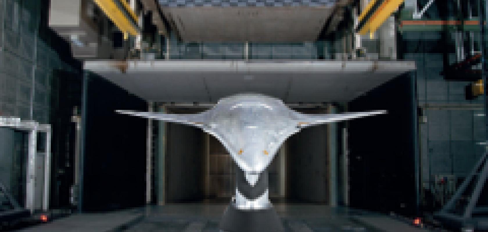
However some researchers are taking the bold but also risky step of moving away from traditional airframes with simulation helping them to evaluate new designs.
A team of researchers at NASA Langley Research Centre are employing simulation techniques to develop novel aircraft designs. The team used a mixture of Mathworks software tools, Simulink and Matlab, to analyse acoustic data and the Parallel Computing Toolbox to accelerate the processing of this data on Nvidia GPUs.
Previously, the engineers were using a legacy program written in Fortran, which took 20 - 40 minutes to process the approximately 2 gigabytes of data generated during each recording.
Mark Walker, principal engineer at Mathworks, said: ‘One of the real problems today, is just trying to find a Fortran programmer; a lot of what drives the aerospace companies is that they have got these trusted analyse, that may be 30-40 years old, originally developed in Fortran. The problem is, very few people speak Fortran anymore.’
Walker continued: ‘However because of Mathworks’ presence in the education sector, there are an awful lot of people, newer graduates in particular, that know exactly how to write the problem in Matlab so that is one of the reasons that you will hear people translating from older Fortran codes into Matlab.’
The researchers found that once the code had been implemented into Matlab the same computation could be completed in just 20 minutes. The addition of GPU computing with Parallel Computing Toolbox cut the time to under a minute.
Walker said: ‘We do see some porting of Fortran into Matlab, it works quite well. Matlab actually grew out of some extensions to some of the things that Matlab could do, so it lends itself to these kinds of applications.’
Walker stated that many of the operations performed in this example such as FFTs and matrix multiplication are GPU-enabled Matlab functions which lend themselves to parallelisation across GPUs.
Another point that Walker stressed was that the using the Parallel Computing Toolbox takes no additional coding as the application automatically maps the processes across available resources. Once the initial Matlab implementation was completed the team found that it only took 30 minutes to get the algorithm working on the GPUs which got the run time of the application down to one minute – a total of 40 times faster than the original Fortran code.
Walker said: ‘As a user I just have to think right here I want to do an FFT on this data, that is a time-consuming and computationally intensive operation and the parallel computing toolbox will work out the best way to achieve that parallelism behind the scenes.’
There are many examples of the work of software developers who wish to make their software as easy to use as possible while keeping or increasing functionality, a tough challenge as models get more complex and many users call for the integration of different simulations.
Mouriaux said: ‘If you really want to benefit from additive manufacturing then now we need to build up knowledge in all the fields like thermal, electronic, and propulsion. If you now want to build using additive manufacturing with integrated systems then you need to have the knowledge of all these things in order to make the best out of it.’
This was a thought shared by Robert Yancey at Altair. He explained that rather than radical change in technology, ‘there is just a lack of good knowledge about how you design for additive manufacturing’. He went on to explain that it would be the convergence of technology and the development of skills that would lead to change in the industry.
Yancey said: ‘I think that’s where combining the additive manufacturing technologies with topology optimisation and then knowledge from companies such as RUAG who have said “Ok, we’re going to make this part out of additive manufacturing; let’s start with a clean sheet of paper and figure out how we’re going to do that”’.
This also rings true in acoustic simulation, Copiello highlighted that MSC software can already integrate different aspects of simulation to deliver a more insightful picture of the real world performance.
Copiello said: ‘If you need more complex acoustics then you need more complex software we have for example Actran VibroAcoustics, which allows you to study acoustic simulation where the both the structure, vibration and the acoustics are solved together.’
Copiello continued: ‘This is important because sometimes you can do first the vibration and then the acoustic and you split the two problems, but sometimes this is not possible. Moreover you need to have a global overview of what’s going on and always be able to evaluate any change in order to be sure that you will meet the acoustic performance that is required.’
Walker from Mathworks also sees the integration of different types of simulation as a trend in the aerospace industry. He said: ‘A trend in both civilian and military operations is the number of systems that integrate together is increasing and the coupling between those systems is also increasing.’
As the integration of different types of simulation and the complexity increases, software developers must abstract some of the unneeded complexity away from the user, delivering increased functionality but not at the cost of making the software more difficult to use.
Walker continued: ‘When you do have that level of complexity is where you will see simulation delivering the most benefit, the number of possible interactions goes up very quickly with the number of times that these systems can connect together, and these can be very complex and subtle.’

Robert Roe is a technical writer for Scientific Computing World, and Fibre Systems.
You can contact him at robert.roe@europascience.com or on +44 (0) 1223 275 464.
Find us on Twitter at @SCWmagazine, @FibreSystemsMag and @ESRobertRoe.