In the not so distant past, mechanical CAD and CAE were the domains of two different groups of engineers, performed with different toolsets. Moving data back and forth between them was a nagging problem, and investigating a change in geometry required the time-consuming process of sending a new geometry to the CAE environment, once again repairing it, reapplying the physics and then redoing the simulation.
Part of the problem is that a CAD geometry isn’t necessarily ideal as a simulation geometry. In a mechanical drawing, an extremely tiny gap between two surfaces won’t necessarily have a major impact. In a simulation, having two geometry domains separated by any distance, however small, can have a huge effect on the results. In addition, CAD drawings might have excessive details that are unnecessary for a meaningful simulation and that would involve a far larger and more-detailed mesh, which increases the simulation time. Thus, it is common practice to perform defeaturing to remove unnecessary detail when creating a simulation geometry.
In recent years, software suppliers have made major strides in reducing these problems. CAE programs are now working with native CAD geometries, which means it is no longer necessary to export a CAD geometry to a standard file format such as IGES or STEP before importing that file into the CAE program. Instead, interactive links between CAD and CAE programs are designed so that if you change the geometry in one environment, it is automatically updated in the other environment. Some CAE companies have created analysis software that literally becomes part of the CAD environment. Most recently, some CAD companies have purchased CAE software with the promise of totally integrated environments.
Benefits of integration
As hinted at earlier, a major benefit to tight integration is that it takes far less time to perform parametric analysis, a very common task where a designer changes the dimensions of a product feature to find the one that achieves optimal performance. In fact, many CAE systems have automated features that sweep through a range of parameters and highlight the results that come closest to the ones you want. This can all happen automatically and quickly when the CAD and CAE packages can pass parameter data back and forth.
Besides such analysis, the ability to tightly couple CAD and CAE is having a fundamental impact on the way engineers work. It’s the rare branch of engineering or R&D where virtual prototyping – that is, trying to find an optimal physical design in software before building a physical prototype for verification – cannot greatly increase productivity and is experiencing widespread usage. Whereas product design used to start with mechanical CAD and then get thrown over the partition to a simulation group for downstream analysis, more and more engineering teams are incorporating CAE at the very early stages of product design and development, making engineering more CAE-centric than CAD-centric.
Let’s now examine these trends as illustrated by recent products from a handful of leading vendors.
Associativity for bidirectional interfaces
For more than a decade, Ansys has provided separate geometry-integration interfaces that let you work directly with an existing native CAD geometry. These modules use the CAD program’s API to transfer geometry data into an Ansys application. The integration also extends to the CAD menu bar, making it simple to launch Ansys simulation programs directly from a CAD system.

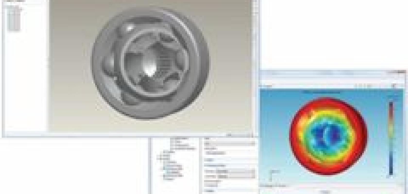
Mentor’s FloEFD.Pro simulation functionality embedded within Pro/Engineer.
These bidirectional connections support the following CAD environments: CATIA V5, Siemens NX, Autodesk Inventor and Mechanical Desktop, PTC CoCreate Modeling, Pro/Engineer, SolidWorks, Solid Edge and VX CAD. With this wide range of support, says director of product management Barry Christenson, the company wants to be CAD neutral. ‘We see many customers who have a need to work with geometries from many different CAD applications, so no matter which mechanical or electronic CAD tools they choose, we provide a consistent environment for simulation.’
The Ansys Workbench environment uses a plug-in architecture to maintain its associativity. Version 12.0 geometry interfaces have been enhanced to import more information from CAD systems, for instance new datatypes such as line bodies and additional attributes, such as colours, coordinate systems, materials with their properties and dimensions. Further, with the Named Selection Manager you can create custom attributes within the CAD application for use directly in Ansys applications for automating modelling, meshing and analysis. The CAD integration solutions also support smart and selective updates of CAD parts so users can update selected parts instead of an entire assembly, which makes geometry updates faster and more targeted with faster results.
The associative capabilities of these geometry interfaces allow users to change a model’s geometry without having to reapply loads, supports and/or other boundary conditions. This associative interface also allows you to drive parametric changes from either the CAD system or Ansys Workbench, making it bi-directionally associative. In Ansys software, you change a part’s dimension without the need to reapply boundary conditions and other physics, to quickly see what effect the new dimension has on, for instance, flow or heat transfer.
You can also perform design iterations with the Parameter Manager, whereby Ansys software automatically changes the dimension of a user-selected geometry feature and runs a fresh analysis for each case. The bidirectional link then allows the CAD model to be updated based on changes within the Ansys Workbench environment. While parametric studies provide the ultimate value for a tightly-coupled associative interface, not everyone is yet taking advantage of it, adds Christenson, who notes that this represents something of a cultural change. While doing such a parametric study was previously a task for the back room, now it’s possible with perhaps 15 additional mouse clicks.
Retain the settings
Adding such associativity is a growing trend among many CAE companies. Comsol, for instance, recently expanded the number of CAD packages it supports in its LiveLink module to now include SolidWorks, Autodesk Inventor and Pro/Engineer. Again, by establishing associativity between the two geometry representations, changing a feature in the CAD model automatically updates the Comsol geometry accordingly; conversely, you can update geometry dimensions in the CAD software from within the Comsol user interface – dimensions are sent to the CAD software where the geometry is regenerated and transferred back to Comsol. Further, settings in the Comsol model are retained on all levels (solid, face, edge and vertex) after a geometry update, and settings are also retained between modelling sessions. Finally, you can create additional geometries such as flow volumes in Comsol, or in an electromagnetic study where you wish to define a domain around the object being studied. To ensure the best compatibility with transferred and imported geometries, the LiveLink products are based on the Parasolid geometry kernel, which is used for geometry operations.
When doing a parametric study, the sequence of operations is now recorded in the model tree. To understand the importance of this, imagine that to create a good mesh for a transferred CAD design you go through several mesh operations. These may consist of defining mesh parameters for certain faces (domains, edges, points) and of actual mesh operations in a certain order. Each operation is saved as a node in the mesh branch of the model tree. When you run a parameter sweep and the geometry is updated, the sequence of mesh operations can be carried out again exactly the same as the first time, which is quite important to keep a good mesh.

Tight integration between Catia V5 (left) and Ansys V12 (right).
The other important requirement is that each operation in the sequence retains its selections as the geometry is updated (for example the swept mesh operation knows which domain to mesh and the mesh size nodes know where they were applied) – this last part is the term to which associativity refers.
CAD-embedded analysis
The next step in integration allows users to perform simulation studies directly in the CAD environment without the need to open up a separate analysis program. This CAD-embedded solution, which obviously works on the native CAD geometry, is what Mentor Graphics’ Mechanical Analysis Division (formerly Flomerics) has been doing for 12 years. You never leave the CAD package and instead click on new menu items that control the analysis process; and if the CAD engineer is careful, there’s generally also no need for geometry repair. Further, post-processing graphics appear on the original CAD model instead of a mesh representation.
‘We don’t ask people to change their design process,’ explains Roland Feldhinkel, product line director, ‘they just see a new menu.’ He adds that this CFD tool has automatic algorithms for meshing and running the solver. He acknowledges that you can’t simply put these tools in the hands of people who don’t understand the physics, but they no longer need to be a PhD to get usable results. ‘Our software takes the “computation” out of CFD, leaving just the “fluid dynamics”.’
While this CAD-embedded software is currently available for Pro/Engineer Wildfire (FloEFD.Pro) and Catia V5 (FloEFD.V5), the company is working on similar products for Siemens NX and Autodesk Inventor. Meanwhile, Mentor also recognises the need for a heterogeneous environment and thus offers Flo.EFD, which works with Inventor, NX, SolidEdge and SolidWorks. This is not an embedded product, but rather a standalone package with the associativity properties described earlier, and yet it provides the automated analysis of the embedded FloEFD products.
CAD/CAE from the same supplier
Given that CAD and CAE are becoming tightly integrated, several large CAD vendors have purchased simulation packages; it’s reasonable to expect that the two will eventually meld into one environment. Perhaps the first step in this direction was taken in 2001 when Dassault Systèmes, which had already acquired SolidWorks in 1997, then acquired SRAC, the original developers of the Cosmos simulation/analysis software. SolidWorks and Cosmos had already been tightly integrated at that time so that you could launch Cosmos from within SolidWorks. Even after the acquisition, Cosmos products are still sold separately.
While SolidWorks is intended for a general-purpose higher-volume CAD market, the Catia line is targeted more towards higher performance within specific industries, and the firm was looking to give it more sophisticated analysis capabilities. According to Tom Bianchi, marketing manager for the Simulia brand products in the UK and Ireland, increased integration is clearly the goal of Dassault Systèmes, which in 2005 acquired the Abaqus simulation software to create a unified FEA product. It thus comes as no surprise that there is an associative interface between Abaqus/CAE and both Dassault’s own Catia V5 and SolidWorks as well as one for Pro/Engineer.
With the Catia V5 interface, for instance, there are three major techniques for passing data. First, automatic associative import allows you to quickly transfer models from a Catia V5 session to an Abaqus/CAE session while both programs are running on the same computer. After the model has been transferred, you can continue to make design modifications in Catia V5 and propagate these to the Abaqus model with one mouse click; any features you create in Abaqus, such as partitions, loads, boundary conditions, sets and surfaces, are regenerated each time you import the modified Catia model into Abaqus. Second, if the two programs are not running concurrently or are on different computers, you can use manual associative import. Using the Catia V5 Associative Interface plug-in, you can save an assembly file to a specified location and import the model into Abaqus or use the assembly file to update an existing model in Abaqus at a later time. Thirdly, direct import is a nonassociative process that does not need the plug-in. The model geometry is saved as a Catia V5 part or product file and can be imported directly into Abaqus.
To get a hint at the capabilities that will eventually be built into Dassault’s CAD systems, consider the ATH (thermal analysis) and ANL (nonlinear structural analysis) capabilities now part of Catia. Both of these are based on Abaqus technology.
With the development of Dassault’s V6 Portfolio, the capabilities of Abaqus will be available on the common V6 architecture, eliminating the need for an associative interface. All the products will be driven by the same interface, with similar toolsets and functionality. The first batch of these products is on the market today as part of the Simulia V6R2010 release – DesignSight Structure. Rather than the coupled interface used now, users will drive Abaqus solver technology from the V6 Viewset environment. Part of this progress is because while Abaqus currently operates with a different geometry creation system than many CAD stems, that package will look quite different in a few years as the V6 portfolio evolves and it will use the same geometry engine as the new V6 product portfolio.

CATIA V5 ATH embedded thermal analysis.
The latest major CAD player who has recognised the importance of this trend and acquired simulation technology is Autodesk, which in early in 2009 acquired Algor. For the moment, the two packages rely on an associative link where you model the geometry in the CAD environment, push a button and the data goes automatically to Algor. And while Algor associativity has been designed to work with a number of major CAD environments, the tightest integration is, of course, with Autodesk Inventor.
Given the amount of time it has taken other CAD vendors to integrate their CAE acquisitions fully into their programs, it’s not surprising that Algor is not yet embedded completely within Inventor. Autodesk does note that it is working on moving Algor’s interface into the Inventor style. It’s also not a stretch to speculate that eventually there will be a total melding of the two packages.
Expanding connectivity
This kind of connectivity is now expanding to other types of analysis packages. Just one example of many is Maple, which is strong in symbolic and numeric computations and interactive examinations of math-based problems. With the firm’s CAD Link Assistant, now supporting SolidWorks, Inventor and NX, users can use Maple’s computational power to analyse and optimise designs. The connectivity allows you to retrieve parameters from a CAD drawing and send new values back to be automatically incorporated in the design. With Maple’s programming language and built-in API commands, users can also create specialised tools for part reconfiguration and optimisation.
