The aerospace industry is often associated with large scale simulations of an entire aircraft or complex parts. As the industry strives for ever-improving performance, it is now optimising at every level – including the components that make up such massive structures.
Such large-scale models of an entire aerospace system are traditionally developed at the onset of the system design process, as Richard Yen, senior vice president for global markets at Altair, explained: ‘These models are focused on simulating the overall system response to all of the intended or expected operating conditions. As these models are refined and developed, aerospace companies have very robust and tested methods to transfer the loads from the system model to an individual component where a much more detailed analysis can be performed.’
There is a high demand for such simulation and modelling of components as the aerospace industry strives to offer continued, improved performance across a range of factors including weight reduction, power management and drag. Rob Harwood, global industry director at ANSYS, explained: ‘The margins for performance increase at all levels in the supply chain are so marginal today that the easy improvements are long gone.’
‘Finding the sources of additional improvement is very, very difficult and simulation is a key technique to rapidly and cost-effectively explore new ideas – even what might appear as simple components such as the bracket on a seat are now being optimised topologically for additive manufacturing, so that they can further reduce weight,’ Harwood added.
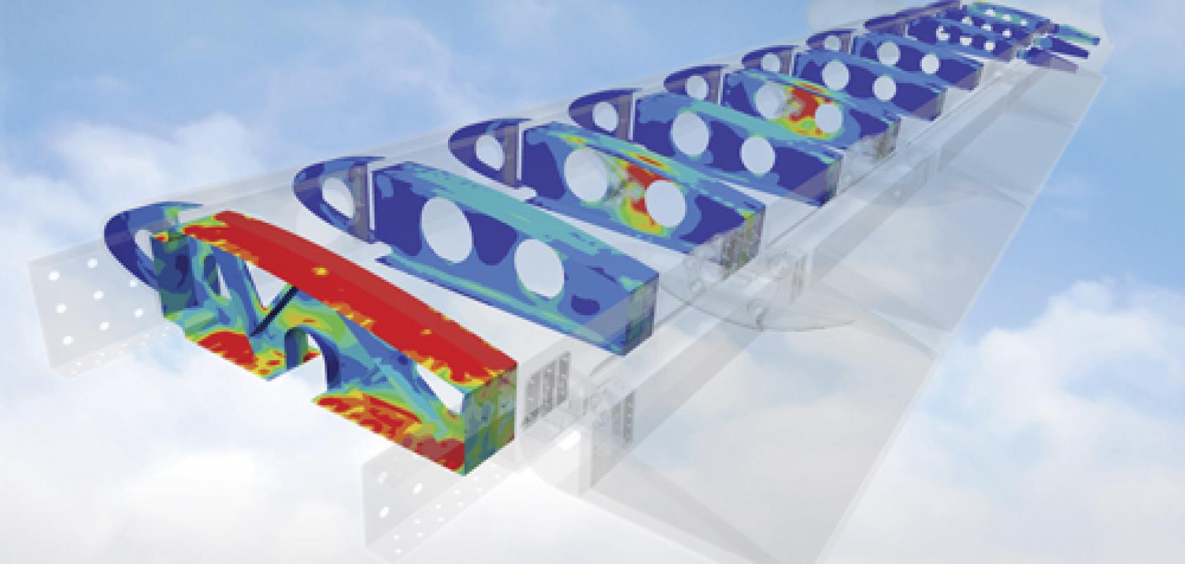
The huge variety of parts to simulate and model in the aerospace industry cannot be overstated. Structural components are probably the most commonly analysed parts using simulation to build on a validation stack from the material coupon, to the component, to the sub-component, to the system. This can be for basic strength, vibration and fatigue-type studies. There are also a lot of structural components in a typical aerospace system, so both local and global simulations are used.
Harwood said: ‘Any component that affects the exterior profile of the aircraft at any phase of flight will likely be subject to aerodynamic analysis to determine its overall impact on the drag and lift of the aircraft and, possibly, even acoustics as noise is becoming more important from the passenger and environmental noise perspective.’
The entire propulsion system and its components are also heavily simulated. The components in the engine operate in the harshest environment – some even operate at temperatures above melting point that without continuous cooling would not last very long.
Harwood added: ‘Simulation is the only cost-effective way to ensure these components can survive the environment they will operate in, before they are tested in very expensive experiments. And these simulations span the entire range of physics, from aerodynamics, structural mechanics, impact, thermal, and so on.’
Electromagnetic modelling is also done for all of the electronic systems, antennas, wireless, sensors, and cabling inside today’s aerospace systems. Yancey said: ‘With the increasing use of electronics in modern aerospace systems, these tools are being used more widely for increasingly complex electronic systems designs.’
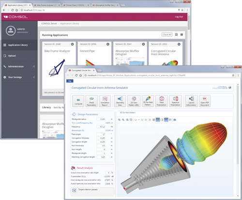
Using a local installation of COMSOL Server product, design teams can give colleagues and customers worldwide access to their simulation apps through a web browser
Bringing it together
The simulation and modelling of all of these components is no mean feat – and not always necessary, depending on the simulation scenario. For example, integrated aerodynamic quantities, such as lift and drag, can be accurately predicted within a certain design range without including the smallest components of a system, according to Dr Cetin Kiris, computational aerosciences branch chief at the NASA Advanced Supercomputing (NAS) Division, who added: ‘But, there are many cases where including full fidelity (geometry and physics) is required to capture more complex phenomena, such as acoustic noise during take-off and landing.’
The main trade-off for such decisions is between the cost of prototype manufacture and testing, versus the cost of component modelling and simulation, according to Guy Johns, lead technologist at the Centre for Modelling and Simulation (CFMS), who added: ‘Modelling and simulation can be more cost-effective, however, it has a higher uncertainty associated with the results and, typically, a more limited dataset compared with real world test rigs.’
As a result, components are rarely modelled in isolation and only in cases of very high fidelity where a particularly complex non-linear behaviour is being simulated. Johns explained: ‘The sheer complexity of the problem under consideration limits the scale to a single component. Complex engineering products are designed for a system level optimum. Over-optimisation of a single component can cause the overall system to become sub-optimal.’
Multi-scale
The aerospace industry has developed very reliable methods to simulate across scales and incorporate the components making up a vehicle.
This helps the sector strike the right balance between the required level of detail to model and simulating for the objective to be met. For example, reduced order modelling (ROM) allows the complexity of a high fidelity case (or real-world dataset) to be reduced.
Multi-physics simulation tools and mixed fidelity modelling also exist, as Kiris explained: ‘Resolving a range of time and space scales is critical to accurately simulating an entire aerospace vehicle. For example, wall boundary layers contain scales that can be many orders of magnitude smaller than the vehicle surfaces which determine them.
‘To handle this, computational fluid mechanics experts utilise multi-scale methods, packing fine mesh resolution only where it is required, such as on smaller components or across flow features such as boundary layers, and utilise coarser discretisations elsewhere,’ he added.
Valerio Marra, marketing director at COMSOL, said: ‘When a multiphysics approach is adopted, a high-fidelity model can be built that reflects reality closely and serves as an accurate predictor of a design’s performance by including all of the physical phenomena involved and being able to describe the interactions as they happen in the real world.’
That said, optimising an entire aircraft system on a single execution is still too big a challenge for the simulation and modelling sector. However, there are means to exchange information through surrogate modelling, which allows multi-fidelity models to use the right fidelity at the right time during the design process. Carlo Poloni, CEO at ESTECO, explained: ‘This means that, for a global decision, you may consider simplified formulas constructed on the basis of the previous simulation being done inside our environment.
‘But once you come to a decision – or possible configuration – you may fire from the top down to the tiny details all the simulations, which are needed at the highest level of fidelity. So, splitting the problem of doing things at the right fidelity in different situations, and in different moments of the process,’ he added.
For example, ESTECO is involved in the Composelector project to develop a multi-scale modelling approach for the selection of composite materials. Poloni explained: ‘A material property at the global level is something that has to be used in the framework of the aircraft simulation, but at the very low level you need the performance of molecules of the materials in relation to the mixture.’
If you look at a composite material, you have to consider the fibres, resin and the interaction between the fibres and the resin at the atomic level. However, when you want to model this even in small components, you need to model these properties. Poloni said: ‘What we can provide is the way to include even the tiniest simulations at the very low scale, up to the higher scale and components, and use that information in the optimisation of the single part.
‘The same analogy could be used at a different scale considering smaller components compared to the complete aircraft,’ he added.
Credit: Mathworks
Multi-fidelity
There are many different scenarios where a multi-fidelity approach is required. For example, an engine manufacturer will need a different level of fidelity in their engine model compared to an OEM, who wants an engine model to integrate into a complete aircraft simulation. Chris Hayhurst, consulting manager at MathWorks, said: ‘That [OEM] needs to run real-time in a pilot-in-loop simulator, and many times faster than real-time for desktop analysis. A supplier may provide a lower fidelity model, which can also serve to protect their IP, however this also adds the overhead of comparing the match or functionality between the two models.’
OEMS are starting to contractually require suppliers to deliver executable models of components or subsystems, prior to delivery of the hardware itself, so that these models can be integrated into the OEMs system-level models, according to Hayhurst, who added: ‘At a technical level, such shared models can foster close engineer-to-engineer co-operation, greater understanding of component behaviour and performance and, at a business level, reduced risk.’
Computational fluid dynamics experts also need to utilise many tools to simulate various vehicles, such as airplanes and rockets. There are a range of flow conditions, such as speeds (low versus high speed), turbulence levels (laminar versus turbulent), time representations (steady versus unsteady). Kiris said: ‘Certain numerical tools are better at certain conditions, and it is the realm of the computation fluid dynamics (CFD) practitioner to select the correct tool to represent the flow physics at the required fidelity.
‘Within NAS, we heavily utilise Navier-Stokes equation based flow solvers, but are now branching out into other representations, such as Lattice Boltzmann-based. It is also common to combine the higher-fidelity methods with reduced order models.’
ANSYS is interested in the Integrated Computational Materials Engineering workflow (ICME) to enable simulation ‘from the atom to the airplane’, according to Harwood, who said: ‘While the practical use of full ICME methods is still somewhat of a vision, progress is being made. Today, it is common to use both global models of the whole aircraft (that use reduced levels of fidelity) to get an idea of load paths and magnitude, and then use these to seed more detailed local models of individual components and subsystems and analyse them in full detail, including multi-scale effects.
‘Of course, as computational power increases and software capabilities become better, the line between these global and local models is blurring, with local models becoming bigger and less local and global models becoming much more detailed. As the margins of performance are squeezed even further, these lines will continue to blur,’ he added.
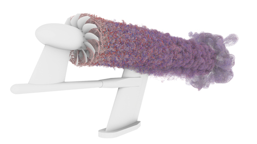
Passive particle visualisation of a pylon-installed, contra-rotating, open-rotor simulation created using the Launch Ascent and Vehicle Aerodynamics (LAVA) code's Cartesian higher-order accurate computational fluid dynamics solver. LAVA was developed in the NASA Advanced Supercomputing Division at NASA's Ames Research Center. Red particles are seeded on upstream blades, blue on aft blades. Solid colours are seeded on tips, while faded colours are on blade trailing edges. (Credit: Timothy Sandstrom, Michael Barad, NASA/Ames)
Safety first
The combination of requirements from a reliability, safety, aesthetics, ergonomic design, time-to-market and environmental aspect represents a huge challenge when simulating components for the aerospace sector.
Marra explained: ‘All of these frequently pull the design in different directions. The use of multiphysics software, such as COMSOL Multiphysics, allows engineers to consider all of these requirements in one go and increase the probability of successfully meeting deadlines.’
Simulation and modelling also allows for the analysis of components in situations where physical testing cannot reveal certain information, because measurements are dangerous, expensive, or even impossible to obtain through experiments. Marra said: ‘Such scenarios include products that operate in space, harsh environments, or at very large or small scales.’
But real-world testing can’t be completely discounted though, for several reasons. ‘For example, some material properties or parameters might be affected by uncertainties in their measurement, hence physical testing is still important,’ Marra added.
This is a particularly pertinent point from a safety perspective, as Harwood explained: ‘The industry is very safety conscious, so any simulation approach must be accurate and validated and ultimately proven in some form of physical test environment.’
‘More and more, a small part is not just some isolated component but is an active part of a system. In that sense, you could say parts are becoming multifunctional – only by considering the breadth of influences (aerodynamic, thermal, structural, electromagnetic) can you truly understand the real-world performance,’ Harwood added.
In other words, no matter how small compared to the scale of the full vehicle, the components of an aerospace system can have a huge impact on its operation.
Sensors are a good example here. An aircraft has a lot of sensors, but the failure of a sensor, or a sensor giving the wrong reading can have a serious impact on aircraft safety or passenger comfort. Marra added: ‘One way engineers understand how large systems work is by considering more components, which also results in their model growing in complexity, and evaluating the effects on the overall performance. Simulation allows them to evaluate and isolate the best case scenario of the impact on each component.’
The components of the simulation software itself also represent one of the biggest challenges when designing and optimising the physical components of the aerospace industry. Poloni explained: ‘If you consider the aerospace industry as a whole, you may have very large departments where each one has a specific competence on specific components.
‘The biggest challenge in designing an aircraft or aerospace vehicle is the integration between subsystems and systems and being able to manage all these integrations inside the same platform,’ he added.
The aerospace industry as a whole is a complex system to untangle at every discernible level – but performances can be optimised through the use of simulation and modelling – one component at a time.
