In the early days of aerospace design, most CFD analysis was done with in-house codes, but the situation is changing. For example, Doug Ball, chief engineer of aero characteristics and flight performance at Boeing, estimates that these days about 20 per cent of his company’s utilisation is with proprietary codes, 30 per cent NASA-originated codes and 50 per cent commercial software.
A universal tool
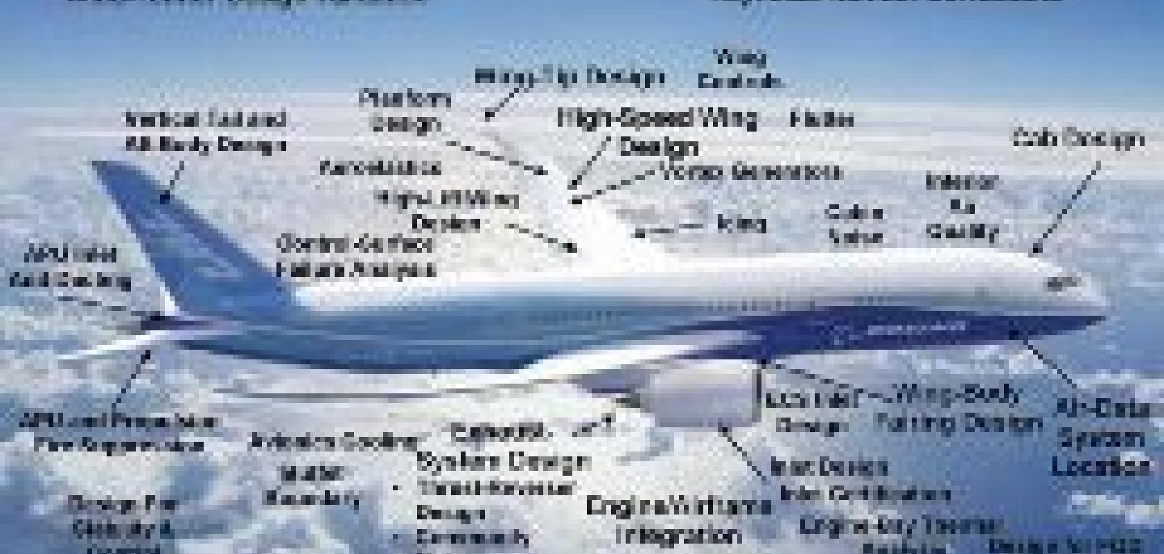
As the image (right) indicates, CFD is contributing to many facets of aerospace design and development, going far beyond the traditional aspects of flow analysis around the wings and fuselage. Of these areas, Ball points to two as being particularly interesting and where CFD has made a major contribution.
One such area is aeroelastic load prediction. The ‘best’ airplane, comments Ball, rarely has the ‘best’ individual components; it becomes the best by having the right balance across many, often conflicting, requirements. In the case of a wing, the trade-off is usually drag versus weight. You can always reduce a transonic wing’s drag by making it thinner – but it will then be much heavier, resulting in an airplane whose performance is not as good. Structural weight is driven by how much depth you have as well as the load’s magnitude. And as any passenger can see through an airplane window, wings often move in response to gusts; these are elastic structures. But as a wing bends and deflects, the loads change. In order to accurately predict both a wing’s performance as well as its weight, you must know how the structure will react to expected loads. Boeing’s processes in this regard have been dramatically improved to the extent that the first loads database for the 747-8F now in development was produced by computer.
A similar aspect deals with the edges of the flight envelope and wing design. The advent of Euler solvers with coupled boundary layers around 1980 made a significant improvement in a wing’s cruise efficiency. Unfortunately, adds Ball, designers still ended up testing many, many wings. While it’s necessary for a wing to have good cruise performance, the lift/drag ratio is not the only factor affecting wing acceptance. Wings must have acceptable off-design characteristics, particularly in the longitudinal axis. Improved CFD tools that model separated flows allow engineers to assess various designs throughout the flight envelope – especially the off-design areas, so that they can weed out unacceptable ones before going to the time and the expense of building a wind tunnel model and testing it.
Almost a flying wing
And that’s if you have access to a wind tunnel, which wasn’t the case for the start-up Propulsive Wing LLC. That firm initially used what company president Joe Kummer refers to as the ‘poor man’s infinite wind tunnel’ – strapping an early three-foot prototype to the roof of a minivan and driving down country roads. In those tests, empirical data showed good correlation with pitch stability from CFD results. In this way, they had confidence that the actual craft would be stable in the air, dramatically cutting down the cost for trial and error.

Turbulence studies, such as finding the laminar-turbulence transition, are critical to evaluating an aircraft wing’s angle of attack and the overall performance (image courtesy of EADS Germany GmbH – Military Air Systems).
The company is now flying prototypes of what looks like a flying wing with a small fuselage. This new class of aircraft uses a cross-flow fan built into the trailing edge of the wing; the fan’s high suction prevents flow from separating off the wing. The result for a given wingspan is as much as 10x the payload and 3x the lift of conventional aircraft. It can also maintain an extreme angle of attack, 40 to 45 degrees, without stalling. And while the aircraft can’t hover, its forward speed at landing can be quite slow, meaning shorter runways. This past summer the company created flying prototypes, made its first formal presentation to the aerospace industry at the CD-adapco StarGlobal Aerospace, Defense and Marine Forum in September, and is looking for partners to commercialise the technology.
Stability and control were an enormous challenge in this very highly coupled system notes Kummer, who adds that without CFD the plane as it is wouldn’t exist. A higher fan speed increases the flow rate; the result is not only higher thrust but, depending on the exhaust angle, it changes the aircraft’s pitch-up/down tendency. Simultaneously, the fan also produces greater suction at the air inlet, which alters the pressure distribution on the wing surface while creating a nose-up reaction due to the direction of rotation. Using Star-CCM+ software, Propulsive Wing was able to successfully understand these relationships and create a stable aircraft.
CFD was also used extensively to simulate sub-systems. In the design of the cross-flow fan propulsion system, simulation results helped optimise the blade and housing geometry. Other studies looked at the effect of propulsive airfoil design parameters – for example fan speed and sizing, duct inlet and outlet locations, and exhaust angle – on lift, drag and pitching moment.
Taming turbulence
Although the underlying equations that define the physics of how aircraft work have been well known for many decades, how these equations are applied continues to undergo considerable refinement. Several interesting examples come from Ansys, says Brad Hutchinson, VP of industry marketing, aerospace and turbomachinery, and such advances are having a major impact in aerospace simulations, because they now enable the study of large unsteady problems.

Air-flow simulation of the Propulsive Wing aircraft using Star-CCM+ from CD-adapco.
Hutchinson explains that the most fundamental and pervasive physical model in aerospace is the turbulence model, because most other models rely upon it. For instance, in turbine combustors, good turbulence models allow engineers to better represent fuel mixing and also study cooling effects, because obstructions and fins induce vortices and eddies in the flow that greatly affect heat transfer. Advanced methods now allow the study of not just the main flow path, but also cavities and secondary flows, where the flow can be more complex and unsteady than the main flow, and the simulation time scales might differ dramatically in various regions. In addition, the study of the transition from laminar to turbulent flow is very important. It can, for example, control the acceptable angle of attack for an airfoil and affect efficiency and performance limits; further, because the turbine blades in engines act as rotating wings, their transition point determines maximum power, heat transfer and efficiency.
Hutchinson adds that in general, when other issues such as grid resolution, boundary conditions, and physical geometry are satisfied, the limiting factor is usually the turbulence model. To date, most CFD codes use Reynolds-Averaged Navier-Stokes (RANS) simulations in which the effects of turbulence are typically represented by an eddy-viscosity, which is often specified with the well-known k-epsilon model. In this regard, Ansys is glad to have the services of one of the world’s preeminent turbulence experts, Dr Florian Menter, and some of his steady-state models have become standard in the industry. Recently, advanced techniques such as Menter’s Shear Stress Transport (SST) model have gained popularity due to superior near-wall and adverse pressure gradient properties, enabling higher resolution and more detailed representation of flow phenomena such as separation, reattachment and heat transfer. In addition, the SST model has been extended to better capture advanced effects such as surface roughness and laminar-to-turbulent transition, which are important for the flow over a wing or an aircraft engine fan or compressor blade.
However, limitations exist with some advanced RANS models, because they cannot simulate a sufficiently wide range of turbulent scales. For most engineering flows, with today’s hardware it takes far too long to simulate all of these scales using a Direct Numerical Simulation (DNS) approach. Meanwhile, hybrid approaches can now simulate the larger scales, which are inherently unsteady, and employ models to represent the smaller scales. Best known is perhaps the Large Eddy Simulation (LES) method, which is appropriate for some flows, but lacks generality because modelling of the small scales is grid dependant.
A more flexible method developed at Ansys is the Scale Adaptive Simulation (SAS) method, which can detect and adjust to the local scales of turbulence. Because it is RANS based, in boundary layers and in other traditional shear flows it produces accurate and economic results, something difficult and potentially expensive for LES-type methods. In unsteady regions where the scales are larger, the SAS model can adapt and produce ‘LES-like’ behaviour, all without requiring user input or control. Perhaps the greatest benefit is that of increased realism and simulation accuracy for a wider range of flows.
Complexities of braking control
Another area where design software contributes to improved aircraft is in control systems. To assist engineers in developing control systems, The MathWorks now provides two products specifically for aerospace engineers: The Aerospace Blockset, its main offering, allows users to model airframes and flight controllers. To support this, it has blocks for co-ordinate transformations, equations of motion, standard atmosphere models and controller scheduling. It works with Simulink to define models and algorithms graphically.

An interface to the MathWorks Aerospace Blockset gives the open-source FlightGear simulator more realistic performance.
Next, the Aerospace Toolbox has functions that can be invoked from Matlab and is aimed more at the aerodynamicist or the system engineer. It provides interfaces to third-party tools (such as the FlightGear simulator described below) and data-storage standards (such as the US Air Force’s Digital Data Compendium, Datcom). The toolbox provides reference standards, environmental models and imports aerodynamic coefficients for performing advanced aerospace analysis. Options for visualising vehicle dynamics include a 6 DoF Matlab animation object and interfaces to FlightGear plus Simulink 3D animations. These options let you visualise flight data in a 3D environment and reconstruct behavioural anomalies in flight-test results.
A heavy user of such products is the Landing Gear Modelling and Simulation Team at Airbus. Group leader Sanjiv Sharma notes that simulation was originally adopted to reduce physical test costs by providing performance predictions, but this technology was soon expanded to detect specification defects. The manufacturer typically outsources the landing gear and its controller; later, though, for internal purposes Airbus needs executable models of both the gear (hydraulic and mechanical components) and the controller for use for simulation studies and in a physical simulator.
One application at Airbus is in brake control algorithms. New control technologies can help to brake an aircraft in a more effective manner, resulting in decreased wear on tyres and brakes while reducing the stopping distance. Advances in tyre-modelling philosophies aim to improve current tyre models in order to get a better prediction of their characteristics. Modelling can lead to more accurate predictions of landing-gear loads, aircraft manoeuvrability and more optimised landing-gear systems.
In this type of work, SimMechanics extends Simulink with tools for modelling 3D mechanical systems. Instead of deriving and programming equations, you can use this multibody simulation tool to build a model composed of bodies, joints, constraints and force elements that reflects the system’s structure. An automatically generated 3D animation lets you visualise system dynamics. You can import models complete with mass, inertia, constraint, and 3D geometry from several CAD systems.
The FlightGear just mentioned deserves a few more words. This open-source flight simulator, currently aimed primarily at civilian flight simulation, is appropriate for simulating general aviation as well as civilian aircraft. The team’s long-term goal is to have FlightGear FAA-approved as a flight training device. Interests in the software range from building a realistic home simulator out of old airplane parts, to university research and instructional use, to simply having a viable alternative to commercial PC simulators. But with the link to the Aerospace Toolkit, it becomes a tool for professionals, as well.
One contributor is Jon S Berndt, chief architect of JSBSim, the default flight-dynamics model for FlightGear. His professional work has involved simulation and prototyping for vehicles ranging from the F-16 to the space shuttle and future manned launch vehicles. Since 1998, Berndt has been working together with co-author Tony Peden on creating JSBSim. This object-oriented, multi-platform aerospace vehicle simulator can be integrated with broader flight-simulation programs (because it provides no visual model) or run in a standalone mode for batch runs.
